Waveguides are special wireless transceiver systems, and they are increasingly used in scenarios that require high communication quality, where there is concern about interference affecting communication effects, and where there is orbital movement. Guoxin Longxin has many years of experience in the design, deployment and application practice of waveguide systems. This article aims to briefly analyze the principles of waveguides and waveguide communication, and introduce the practical applications of waveguides with examples of metro train-ground communication and remote control applications of heavy machinery.
I. Concepts, Principles and Types of Waveguides
1. What is a waveguide?
A waveguide is a structure used to directionally guide electromagnetic waves. In electromagnetics and communication engineering, the term “waveguide” can refer to any linear structure that transmits electromagnetic waves between its endpoints. However, its original and most common meaning refers to a hollow metal tube used to transmit radio waves. Such waveguides are mainly used as transmission lines for microwave frequencies, and are employed in microwave ovens, radars, communication satellites, and microwave radio link equipment to connect microwave transmitters and receivers to their antennas. They are particularly widely used in high-frequency microwave communication scenarios.
Common waveguide structures mainly include parallel twin wires, coaxial cables, parallel plate waveguides, rectangular waveguides, circular waveguides, microstrip lines, planar dielectric optical waveguides, and optical fibers (note: optical fibers that transmit lasers are also an application of waveguides). From the perspective of guiding electromagnetic waves, they can all be divided into internal and external regions, with electromagnetic waves confined to propagate in the internal region (requiring the satisfaction of the transverse resonance principle within the waveguide cross-section).
In 1893, J.J. Thomson first proposed the concept of a waveguide. In 1894, O.J. Lodge was the first to experimentally demonstrate a waveguide. In 1897, Lord Rayleigh was the first to complete the mathematical analysis of propagation modes in hollow metal cylindrical waveguides (McLachan, 1947).
Typically, waveguides specifically refer to hollow metal waveguides of various shapes and surface waveguides. The former completely confines the transmitted electromagnetic waves within the metal tube, also known as closed waveguides; the latter restricts the guided electromagnetic waves to the vicinity of the waveguide structure, also known as open waveguides.
Dielectric waveguides use solid dielectric rods instead of hollow tubes. Optical fibers are dielectric waveguides operating at optical frequencies. Transmission lines such as microstrips, coplanar waveguides, strip lines, or coaxial cables can also be considered as waveguides.
In terms of the practical application of waveguide communication, the supporting wireless equipment must undergo specialized design and matching. For high-bandwidth, high-definition video, and high-reliability “three-high” application scenarios of waveguides, the most typical example is Guoxin Longxin’s iMAX-8000W series of dedicated mobile communication systems for waveguides.
2. Communication Principles of Waveguides
A waveguide is a hollow metal tube with a very smooth inner wall or a tube lined with metal, which is used to transmit ultra-high frequency electromagnetic waves, allowing pulse signals to be transmitted to the destination with minimal loss. The inner diameter of the waveguide varies depending on the wavelength of the signal being transmitted. It is mostly used in radio fields such as centimeter-wave and millimeter-wave radio communication, radar, and navigation. Currently, common types include rectangular waveguides, circular waveguides, semicircular waveguides, Ku waveguides, radar waveguides, and optical waveguides.
When the frequency of radio waves increases to the centimeter-wave band (3000 MHz to 30 GHz) and millimeter-wave band (30 GHz to 300 GHz), the use of coaxial cables is restricted, and metal waveguides or other wave-guiding devices are often used for transmission. The advantages of waveguides are small conductor loss and dielectric loss, large power capacity, no radiation loss, simple structure, and ease of manufacturing.
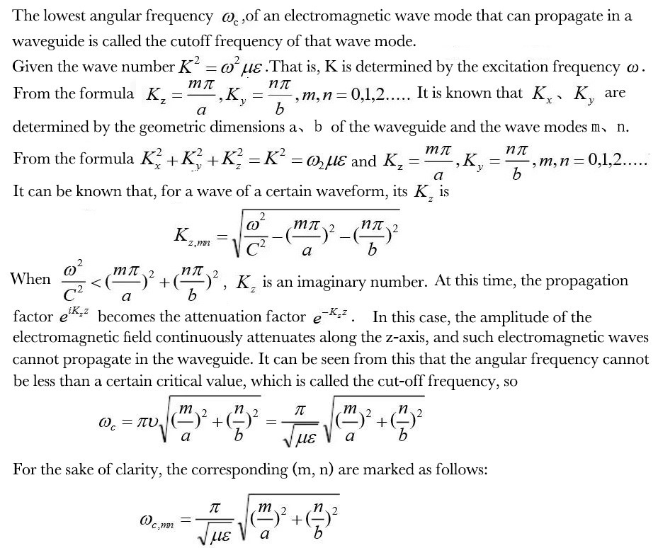
The electromagnetic field in a waveguide can be solved by combining Maxwell’s equations with the boundary conditions of the waveguide. Unlike ordinary transmission lines, TEM modes cannot be transmitted in waveguides, and electromagnetic waves have severe dispersion during propagation. The dispersion phenomenon indicates that the propagation speed of electromagnetic waves is related to frequency.
Surface waveguides are characterized by the presence of electromagnetic fields outside their boundaries, with the propagation mode being surface waves. In the millimeter-wave and submillimeter-wave bands, metal waveguides have increased losses and are difficult to manufacture due to their small size. The use of surface waveguides, in addition to good transmission performance, has the main advantages of simple structure, easy fabrication, and the ability to have planar structures required for integrated circuits. The main forms of surface waveguides include dielectric lines, dielectric image lines, H-waveguides, and image concave waveguides. In short, RF adapter cables are applications of surface waveguides.
The electromagnetic waves in metal tube waveguides can be imagined as traveling in a zigzag path in the waveguide, reflecting back and forth between the walls of the waveguide. For the special case of rectangular waveguides, an accurate analysis can be based on this view. Propagation in dielectric waveguides can also be viewed in the same way, where waves are confined to the interior of the dielectric by total internal reflection on the surface of the dielectric. Some structures, such as non-radiative dielectric waveguides and high-retention lines, use both metal walls and dielectric surfaces to confine waves.
The iMAX-8000W operates in the full 5 GHz frequency band, which belongs to the centimeter-wave range. Its frequency characteristics determine that the waveguides matched with it are mainly metal tube waveguides.
Field distribution:
A possible field distribution that satisfies the boundary conditions of the waveguide cross-section is called a mode of the waveguide. Different modes have different field structures, and they all satisfy the boundary conditions of the waveguide cross-section and can exist independently. The most common field distributions are rectangular distribution and circular distribution. Take the rectangular field distribution as an example:
There can be infinitely many TMmn modes in a rectangular waveguide. The mode indices m and n represent the number of standing wave maxima of the electromagnetic field along the wide side a and the narrow side b of the waveguide, respectively, where m, n = 1, 2, … The simplest one is the TM11 mode. Similarly, there can also be infinitely many TEmn modes, with m, n = 0, 1, 2, … but they cannot be zero simultaneously. The lowest mode in a rectangular waveguide is the TE10 mode, which has the longest cutoff wavelength λC = 2a. Therefore, it is possible to achieve single-mode transmission in the waveguide. The TE10 mode, also known as the dominant mode in rectangular waveguides, is the most important mode in rectangular waveguides. In practical applications, rectangular waveguides all operate in the TE10 mode.
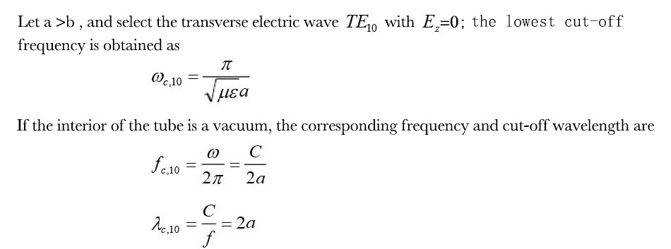
Conclusion: The maximum wavelength that can be transmitted in a waveguide depends on the dimensions of the waveguide. Since the geometric dimensions of a waveguide cannot be made excessively large, waveguides are most widely used in the centimeter wavelength band.
3. Types of Waveguides and Slotted Waveguides
Common waveguides can be divided into ordinary waveguides, slotted waveguides, and open waveguides. Open waveguides are rarely used due to significant signal attenuation and inconvenience in later maintenance, so they will not be elaborated on in this article.
An ordinary waveguide is a hollow metal tube with a very smooth inner wall or a tube lined with metal. It is used to transmit ultra-high frequency electromagnetic waves. Common cross-sectional shapes include rectangular and circular. Pulse signals passing through it can be transmitted to the destination with minimal loss. The inner diameter of the waveguide varies depending on the wavelength of the transmitted signal. Waveguides exhibit the characteristics of a high-pass filter in a circuit: they allow signals above the cut-off frequency to pass through, while signals below the cut-off frequency are blocked or attenuated. Ordinary waveguides are usually used for communication between short-distance devices, or for signal transmission between a device’s antenna port and the antenna.
Slotted waveguides are mainly used to solve the scenario of linear “track-type movement” because slotted waveguides can be deployed over long distances (from hundreds of meters to hundreds of kilometers). Therefore, among different types of waveguides, slotted waveguides are the most widely used:
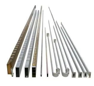
Due to the high price of copper, aluminum is relatively cheaper, and it is easy to process and transport. Therefore, at present, aluminum alloy is the most commonly used material for slotted waveguides, and the rectangular aluminum alloy waveguide is the one most frequently used in conjunction with iMAX wireless systems.
Currently, waveguides are most widely used in the communication and control systems of subways. Different from the GSM-R mode adopted for the bidirectional transmission of train-ground wireless signals in the national high-speed railway signal system, in subway signals, three modes are mostly used: directional antennas, leaky cables, and slotted waveguides. Leaky cables, also known as “leaky wave cables”, have a relatively low transmission frequency band, large loss, and small information bandwidth. Although their price is relatively low, they are not widely used. In contrast, slotted waveguide communication has been more widely applied due to its wide transmission frequency band, small transmission loss, high reliability, and strong anti-interference ability.
II. Applications of Slotted Waveguide Systems
1. Application of Waveguides in Rail Transit
With the development of urbanization in China, the urban population is gradually increasing, and the pressure of travel is gradually rising. Under such circumstances, the subway has become a very important way for people’s daily travel, thus driving the construction of subway projects in many cities. With the continuous application and development of subway wireless communication technologies, waveguides are very important signal transmission equipment, and we need to make good use of this equipment to better realize the efficient and stable operation of the subway.
In subway operation, the signal system can be said to be an important guarantee for the safe and stable operation of the subway. In actual engineering construction, it is necessary to fully connect with reality, and through the good application of waveguide technology, ensure the efficiency, quality and anti-interference ability of data transmission while realizing the safe operation of trains.
In practical application for wireless data transmission tasks, it not only has high reliability and low loss, but also has very high anti-interference performance. In practical application, a wireless receiver can be installed near the waveguide equipment to receive its slot radiation signal, and after certain processing, more effective data information can be obtained. Generally, the supporting transmission units for waveguides include coaxial cables, leaky waveguides, double-sided flanges, wireless access equipment (BS & CPE), and terminal loads.
Engineering and technical examples of the application of waveguides in subway signal systems:
In the current subway signal system, in order to make the system more stable and ensure safer train operation during driving, it is necessary to strictly select wireless communication technologies and put forward higher requirements. Adopting the most advanced and reliable wireless communication technologies and using waveguides to transmit the system’s wireless signals is the basic guarantee for the communication quality of the signals.
The waveguide information network is used to ensure the continuous two-way transmission of information between the train and the local ATS (Automatic Train Supervision) – Automatic Train Supervision System and the control center. The waveguide information network is composed of multiple waveguide information network communication units and on-board waveguide information network mobile stations:
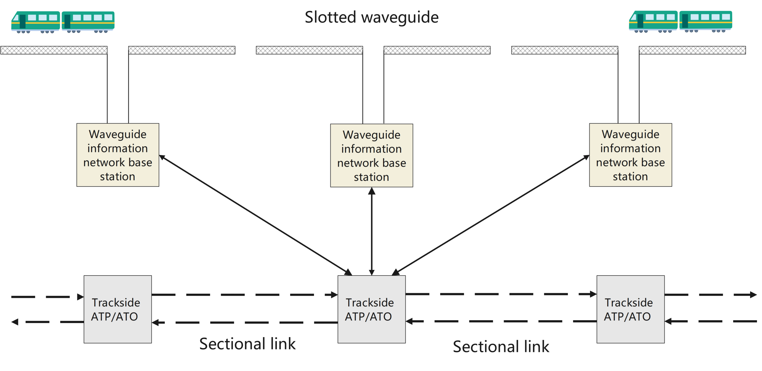
Waveguide information network structure
The waveguide information network base stations are connected via wires to the trackside ATP (Automatic Train Protection)/ATO (Automatic Train Operation) – Automatic Train Protection/Automatic Train Operation systems. The trackside ATP/ATO systems form a sectional link through optical fibers, pigtails, optical distribution frames, optical transceivers, and other components.
To ensure network security, the wireless network between the waveguide information network base stations and mobile stations must not adopt the open IEEE 802.11 protocol (Wi-Fi standard). Instead, it is recommended to use the PowerX wireless technology, an exclusive, more professional private network protocol of the iMAX wireless system. This technology is based on TDD (Time Division Duplex) OFDM (Orthogonal Frequency Division Multiplexing) and MIMO, enabling more efficient signal processing.
2. Application of Waveguides in Remote Control of Heavy Machinery
Currently, in scenarios involving intelligent remote control or unmanned operation of heavy machinery in many industries, for heavy machinery that moves linearly back and forth along tracks within a certain area or channel—such as yard cranes, quay cranes, rail-mounted gantry cranes, and overhead traveling cranes—the adoption of waveguide wireless systems can significantly enhance the system’s wireless anti-interference capability and increase effective bandwidth. Especially for remote intelligent control that requires simultaneous transmission of control signals and high-capacity high-definition videos, the slotted waveguide wireless solution is the optimal choice.
Taking the application of waveguide wireless systems in a certain overhead traveling crane as an example, its network topology diagram is as follows:
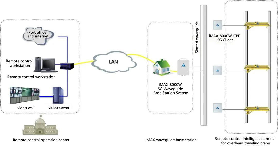
In projects involving remote intelligent control of overhead traveling cranes, waveguide systems are typically deployed along the direction of crane movement, mounted longitudinally beneath the girder. The waveguide base station (BS) is usually placed on one side of the waveguide, while a wireless client device (CPE) is installed on the crane. The antenna of the CPE moves parallel to the waveguide, maintaining a consistent distance of approximately 20-30 cm.
Waveguide systems are generally reliable and stable, but like optical cables, as a single system, they inevitably face the risk of system failure due to single-point faults. From the perspective of reliability design, only redundancy can truly improve system reliability. Therefore, adopting a “pure air interface wireless system” for redundant hot backup of the waveguide system is the optimal solution for such applications. Specifically, an additional independent pure wireless private network system is built to implement VRRP hot backup redundancy with the waveguide system, or a dual-link data mirroring configuration is adopted to further enhance the overall reliability of the system.
For more detailed information on the application of waveguide systems in heavy machinery, please refer to the article Application of Waveguide Communication Technology in the Field of Intelligent Control for Heavy Machinery.
III. Configuration and Installation of Slotted Waveguides
1. Principles for Waveguide Configuration
Depending on different working conditions, the actual configuration of waveguides shall follow the principles below:
1) Signal coverage: Ensure comprehensive coverage of wireless signals, while maintaining good signal strength to achieve higher signal transmission quality.
2) Planning and design: Design and plan the system in a scientific and reasonable manner, striving to meet the system configuration requirements with the minimum number of access devices to reduce costs.
3) Redundant power and roaming handover: Based on the actual engineering conditions, ensure that each waveguide section has a certain amount of redundant power, and avoid frequent roaming handover between different devices during actual operation.
4) Waveguide cavity and waveguide antenna: Practice in waveguide configuration has shown that for MIMO communication systems with simultaneous transmission of dual signals (vertical V and horizontal H), the optimal waveguide design is a “single-tube dual-cavity” structure. This design not only reduces the difficulty of installation and commissioning but also concentrates signals, facilitating communication with directional high-gain, small-angle waveguide antennas. It not only improves the stability of the system but also enables longer-distance deployment of waveguides and higher bandwidth capacity. Multi-waveguide and multi-cavity designs are considered unprofessional.
5) Reliability of the waveguide system: In a sense, a waveguide is a special type of antenna that must work with highly reliable wireless network equipment (such as the iMAX-8000W). Therefore, as a passive device, the waveguide itself has no bearing on system reliability. Improving the reliability of the waveguide system relies on reliability technologies, such as the VRRP (Virtual Router Redundancy Protocol) hot standby routing technology and multi-link data mirroring technology of the iMAX-8000W. These technologies not only enhance system reliability but also enable smooth roaming and handover between base stations.
The most common method to improve the reliability of the waveguide system is to implement dual-link hot standby redundancy between the waveguide system and a pure air interface wireless system. For knowledge about the reliability design of wireless systems, please refer to the article How to Ensure the Reliability of Wireless Network Communication Systems?
6) Length of waveguide system and multi-mode wireless base station:
Ordinary single-air-interface wireless devices, with only one wireless interface, can connect to a maximum of 2 waveguide segments (via a 1:2 power divider). However, their driving capability varies significantly due to limitations in device signal strength and sensitivity indicators. In the industry, the communication length of many waveguide systems does not exceed 150 meters. Thanks to the excellent communication capability of the iMAX-8000W, the configured length of its waveguide is generally within 400 meters (200 meters on each side). Therefore, in waveguide application scenarios, the iMAX-8000W saves more resources and costs, with obvious advantages.
The dual-mode base station (BS) of the iMAX-8000W system is equipped with two wireless interfaces, and can connect to a maximum of 4 waveguide segments (via 1:2 power dividers). The configured length of its waveguide is generally 800 meters × 2 (200 meters × 2 on each side, 400 meters on each upper and lower part). In multi-parallel channel scenarios (such as remote control of yard cranes), a total of 800 meters of waveguides in the upper and lower channels can be connected using only one set of waveguide base station (BS) equipment, which saves a lot of costs for users. The reduced number of roaming events also further simplifies the system, ensuring system availability and reliability.
Dual-mode base stations are also very suitable for application in the case of double-track single tunnels, which can be said to be a very practical and economical connection method. If the tunnel type is double-track, it is necessary to carry out the connection based on the actual situation and flexibly select the number of waveguides of different lengths. Regardless of our choice, it is necessary to ensure that data transmission quality is given top priority, and avoid situations where transmission quality is not guaranteed simply for cost saving.
2. Precautions for Waveguide Installation
Taking the installation of waveguides in subways as an example, the installation location can be flexibly chosen according to the on-site environment. They can be installed not only on the top of the tunnel but also on the ground.
1) Tunnel top: When installing on the tunnel top, expansion bolts are generally used to mount brackets on the top, and the waveguides are placed on these brackets. During installation, a fixed bracket is installed on the wall-side of each waveguide segment, and a sliding bracket is set every 4 meters. The distance between the brackets and the flange must be more than 200 meters to save construction costs. A gap of 60 to 70 centimeters should also be maintained between each waveguide segment to save materials. Near the platform, a corresponding antenna should be installed at the end of the waveguide and connected using a coaxial cable.
2) Ground: Waveguides are also installed using bracket fixation. Height-adjustable brackets can be set according to the on-site environment to meet relevant technical requirements. During installation, a sliding bracket is set every 3 meters, and other technical requirements are the same as those for top installation.
Corresponding to the waveguide installation methods are the installation methods of the iMAX-8000W on-board client system, i.e., the installation methods of the wireless device WCS on subway vehicles, which include roof installation and undercarriage installation. The specific location should be adjusted according to the type of accessed service and the requirements of the management party.
Meanwhile, waterproofing work must also be emphasized. It is necessary to prevent water flow from affecting the equipment and ensure a constant distance between the waveguide and the train’s wireless antenna during installation. In addition, after the installation of the slotted waveguide, a tightness test should be conducted, and nitrogen should be filled to prevent external water from entering through “positive pressure”.
In general, to achieve better data transmission performance, the distance between the slotted waveguide and the wireless antenna should be kept between 20 and 40 centimeters. The waveguide antenna matched with the iMAX-8000W is a specially customized waveguide antenna.
3. Joint Commissioning and Testing of Waveguides and Equipment
After the installation of waveguide equipment is completed, it is necessary to carry out debugging in conjunction with iMAX’s dedicated waveguide communication product series—the iMAX-8000W series of dedicated mobile communication systems for waveguides. This ensures that the waveguides can achieve better transmission performance in practical applications and that the transmission of wireless signals meets operational requirements.
1) Transmission test: The main purpose of this work is to verify the attenuation of the target waveguide. Specifically, a continuous signal with known intensity and frequency is injected into the waveguide, and measuring instruments are also installed at the terminal of the waveguide to detect the signal. During this test, it is necessary to ensure the completeness and comprehensiveness of the test, so that it can fully cover all waveguide sections. The difference between the measured signal strength and the injected signal strength is the attenuation of the waveguide, which must fully meet the design requirements.
2) Echo test: This test is mainly to check for foreign objects in the waveguide to ensure better smoothness. In terms of testing equipment, there are mainly fault locators and microwave testers. By injecting high-frequency signals with known parameters, the return signals are measured on the same side of the waveguide. Then, based on the mismatch of the waveguide, the position of the foreign object is determined and technically removed.
In general, the application of waveguides, especially slotted waveguides, in many fields such as rail transit (subways), intelligent control of port heavy machinery, and intelligent control of overhead traveling cranes in metallurgical production, is becoming increasingly mature and popular. With the birth and widespread application of high-performance, high-quality iMAX-8000W series dedicated mobile communication systems for waveguides, waveguide communication will be adopted by more users. It will meet the high-speed link demands of occasions with high requirements for communication stability, strong interference, and mobile communication, and help promote the further popularization of high-reliability and intelligent applications.
first